

Record ID:
55Agency:
South Wales and Gwent PoliceNTSB Identification:
Legislation:
Accident Occured:
2000-03-14 in 9 Coryton Drive, Cardiff, Wales, UKAircraft:
Aerospatiale AS355F2, G-SAEWInjuries:
3 uninjured,Report Header:
Report courtesy of United Kingdom Air Accidents Investigation Branch AAIB Bulletin No: 1/2001 Ref: EW/C2000/04/05 Category: 2.2 Aircraft Type and Registration: Aerospatiale (Eurocopter) AS355F2, G-SAEW No & Type of Engines: 2 Rolls Royce Allison 250-C20F turboshaft engines Year of Manufacture: 1990 Date & Time (UTC): 21 April 2000 at 1937 hrs Location: 9 Coryton Drive, Cardiff, Wales Type of Flight: Public Transport Persons on Board: Crew - 3 - Passengers - None Injuries: Cr
Full Report:
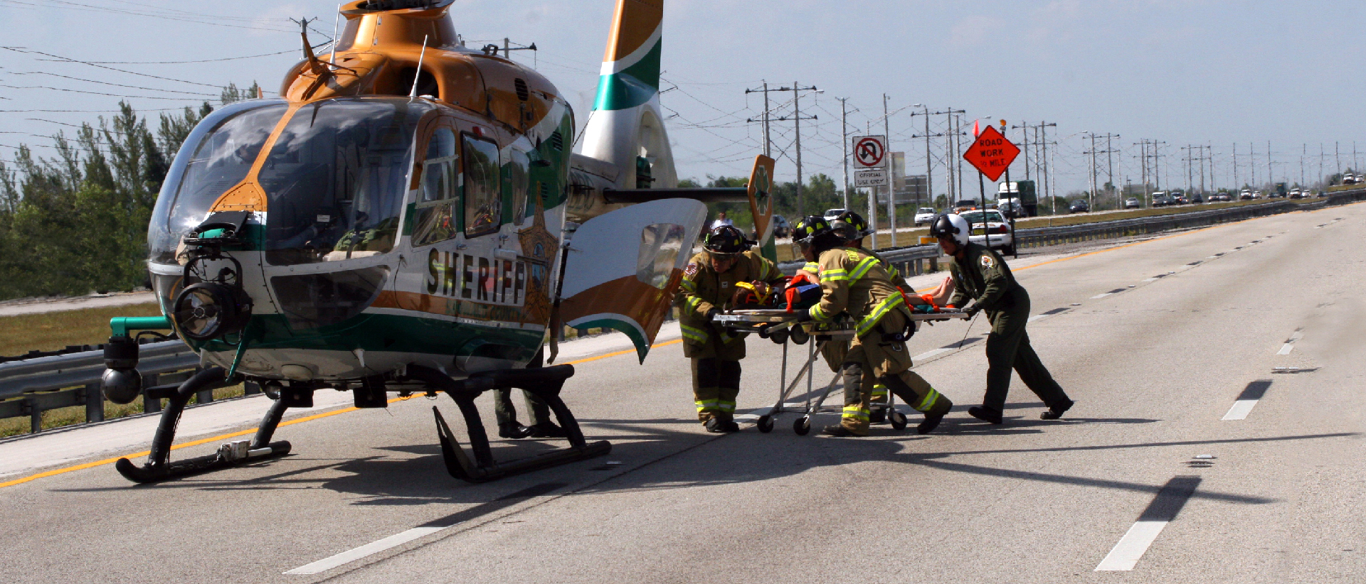
The Twin Squirrel helicopter was operating in the Cardiff area on behalf of the South Wales and Gwent Police forces. It was based at Cardiff Heliport, from where it was normally available on call for 18 hours per day. The company operating the helicopter employed 5 pilots who regularly flew this aircraft, the sole example of the type operated by this company. The pilot reported for duty at 1700 hours and in response to a callout was airborne on his first flight of the evening at 1855 hours. There were two qualified police observers on board. The helicopter lifted off from the heliport, flew north for 10 minutes and then spent some 10 to 20 minutes on task. While on task the helicopter was mainly in the hover and the pilot reported that it responded normally to all control inputs. When the first task was completed the helicopter flew south back towards the heliport and was diverted to a second task which involved hovering at 500 to 600 feet agl over a residential area near the M4 motorway. The visibility was good with a last reported surface wind of 200/12 kt. Sunset was at 1910 hours and daylight was fading, but the pilot was still able to fly by visual reference. The helicopter had been hovering in the area for about 10 to 15 minutes, facing in a south-westerly direction, when it suddenly made an uncommanded yaw to the left through some 180 degrees. The pilot immediately applied full right yaw pedal to counter this yaw. However, although the helicopter stabilised for a moment, it then yawed more rapidly to the left. At this time he called out to the two observers on board to warn them of a problem with the helicopter. He partially lowered the collective lever in an attempt to regain control and applied some forward cyclic to gain forward motion and airspeed, but the helicopter then entered a steeply spiralling/yawing descent to the left. The pilot realised that he would not be able to recover full control of the helicopter and abandoned his attempt to fly out of the situation. He concentrated on keeping the helicopter as level as possible whilst looking out through the right side window for visual reference, since he found the forward view too confusing due to the rapid yawing motion. He adjusted collective to achieve what he judged to be the best combination of rate of descent against yaw, and when he caught sight of the surface in his peripheral vision he pulled the collective lever fully up to cushion the impact. The helicopter came to rest embedded in the roof of a house, as shown in Figure 1, having broken through the rafters and settled in a right side low attitude. After the impact, the pilot was unable to reach the engine fuel controls on the overhead panel until he had unstrapped himself from his seat. However, when he was able to reach the speed select and emergency fuel shut off levers he could not move them due to impact induced distortion of the overhead panel. He was able to activate both fire extinguishers and to turn the battery switches OFF. The observer in the front left seat escaped through his door on the left side of the helicopter and the rear seat observer climbed past the pilot and exited through the same door; the pilot then followed. The three occupants, all of whom were wearing protective helmets, were uninjured and later used a ladder to climb down from the roof. There were a large number of witnesses to the accident. They all described seeing the helicopter hovering for some time above the houses and then swinging suddenly to its left, spinning around and descending. A video recording taken by one witness showed the helicopter in an apparently normal hover some 2 minutes before the accident. Pilot experience The pilot had been employed by the operator for 7 months and in that time had flown 159 hours on this helicopter. Prior to joining the company he had flown helicopters in the Royal Navy for a number of years. In 1993 he was involved in an accident to a Westland Sea King helicopter in which the tail rotor drive shaft had failed. He had witnessed, on that occasion, a change in engine sound or mechanical noise associated with the loss of control, whereas on this occasion he had not heard any such changes. Impact sequence The helicopter had descended vertically at relatively low speed onto the apex of the pitched roof of a semi-detached house in such a manner that its centre of gravity was essentially over the centre of the roof. This had resulted in the roof being crushed down to the tops of the supporting walls, where the helicopter had come to rest in a stable position, partially on its right side and almost directly over the stairwell of the house. The tail boom, which was overhanging the front wall of the house, had suffered a downward bending failure as a result of inertial loading, and this had alleviated impact forces in the region of the tail rotor. At least one main rotor blade (MRB) had struck the rear wall of the house whilst under power, precipitating failure of the main rotor gearbox (MRG) supporting structure in the fuselage. The MRG had toppled forward and come to rest lying across the upper front right side of the cockpit. Relatively minor damage had been caused to surrounding houses and cars by roof tile shrapnel generated by main rotor blade contact. Although some fuel had been released into the house after the impact, fire had not occurred. The helicopter was recovered by crane (as shown in Figure 2) and with the assistance of personnel from the Royal Air Force Aircraft Recovery and Transport Flight from RAF St Athan. During the process of removing the helicopter from the roof, it became apparent that it was sufficiently structurally intact to be placed safely upon its skids for an initial examination. It was later transported to the AAIB at Farnborough for detailed examination. Helicopter history The helicopter had been manufactured by Aerospatiale (now part of Eurocopter) in 1990 and was initially operated overseas. It was placed on the UK register in the Transport (Passenger) Category in January 1997, with a total time of 1,212 hours, and equipped for the Police role at that time. The last maintenance was performed at 2,877 hours, some 11 days and 20 flying hours prior to the accident, at which time Service Bulletin (SB) 65.00.15 had been implemented. This SB embodied manufacturers modification MOD 076551 to the tail rotor (T/R) pitch change unit (PCU). Initial examination Before the helicopter was transported from the site, the opportunity was taken to remove the battery, drain the fuel tank and conduct a brief visual examination of the damage. During this examination it became apparent that the T/R PCU, which was mounted on the tail rotor support/drive shaft, was in a partially disrupted state, as shown in Figure 3. However, the PCU did not appear to have suffered any direct damage as a result of the impact. It was also readily apparent that the type of disruption evident on the PCU could have caused a loss of yaw control. PCU description A detailed cross section of the PCU is included at Figure 4. The PCU has three main elements which include: a rotating spider driven from the tail rotor via two pitch control links and which rotates with the tail rotor drive shaft; a stationary spider which is connected to a control bellcrank pivoted at the tail rotor gearbox; and a sealed ball bearing fitted between the two. The PCU assembly controls the tail rotor blade pitch angles by sliding along the tail rotor drive shaft to positions relayed by the bellcrank which is linked to the pilots yaw pedals. This PCU arrangement is common to the AS350 (single engine) and the AS355 (twin engine) versions of the Squirrel helicopter. The stationary spider is in effect a bearing housing in which the outer race of the bearing is retained by both a small interference fit and a bolted cover plate. The inner race of the bearing is fitted near the inboard end of the rotating spider shaft, and is protected with several flanged spacers which act as labyrinth seals intended to both exclude water and retain grease. The inner race is retained by a slight interference fit on the rotating spider shaft and clamping forces transmitted through the spacer seal flanges from a steel nut screwed to the shaft end. After an initial bedding torque has been applied to the nut and released, the nut is re-torqued within lower specified limits and then locked by two tab washers. The steel nut engages with only 3 to 3.5 turns of the thread on the aluminium alloy shaft and, in order to minimise the effects of vibration, a thin PTFE loaded varnish (D148) is applied to the bearing locating areas of the rotating and stationary spiders as an anti-fretting coating. Detailed examination Apart from the disrupted condition of the PCU, no other evidence of pre-accident defect was found during the subsequent detailed examination of the flying controls and rotor transmission systems. The investigation therefore concentrated on the apparent failure of the T/R PCU. Before the PCU was removed and stripped for examination, a more detailed visual inspection revealed that the bearing clamping nut had become detached and that this was associated with failure of the threads on the aluminium alloy shaft. This in turn had allowed the rotating spider to displace axially relative to the stationary spider, effectively leading to a loss of control of T/R blade pitch angle and hence of yaw control of the helicopter. The PCU was subsequently separated into its component parts and these were then subjected to detailed examination. Rotating spider Several of the components comprising the PCU exhibited evidence of pre-accident damage, particularly the 'shaft' end of the rotating spider. As shown in Figure 5, at the bearing location position there was clear evidence of relative movement, in an axial sense, of the bearing inner race which had deformed and fretted the shaft surface, but this had mainly occurred at the two edges of the race. It was also clearly apparent that the aluminium alloy shaft threads which normally engage with the steel nut had sheared near the base of the threads. These threads had been truncated due to shearing in a manner which suggested that the nut had rocked as it had displaced inboard. Damage was apparent to both sides of the keyway recess in the threaded region, which secured the tabs of the nut locking washers, and this damage appeared consistent with heavy contact by these tabs as the assembly came apart. Several other features were present on this section of the spider. Figure 6 shows a comparison between the shaft end of two similar rotating spiders removed from service with that from G-SAEW. Item (a) was taken from an AS355 which had been involved in a ground fire accident but which otherwise represented the typical condition of a serviceable rotating spider shaft with respect to the bearing location area. Item (b) was removed from service following loss (or reduction) of the clamping force across the inner race, which had resulted in wear of the bearing inner race location area of the spider shaft due to spinning of this inner race. This was reportedly the most common type of damage resultant from loss of nut torque in service. Item (c) shows the spider bearing area from G-SAEW. The green coloured D148 anti-fretting varnish should normally be present over the parallel section of the shaft, as seen on items (a) and (b) but not, as specified in the relevant Maintenance Manual, on the shoulder or undercut area. As may be seen from item (c), there was no evidence on the shaft from EW of this varnish in the bearing support area or on the area between the latter and the threads, but clear evidence of its presence on the shoulder and in the undercut was evident. This varnish should normally be between 10 and 20 microns thick ( 0.01 mm to 0.02 mm), which was the case with items (a) and (b). On item (c), where the varnish was present there were at least two layers, the topmost layer of which was relatively thick (approximately 0.05 mm) but was loosely adhered and could be readily flaked off. The surface of the shaft, over its parallel section and including the varnished area, also showed evidence of fine scoring consistent with the use, at some time, of a mild abrasive. On the spider shaft from EW evidence of corrosion was found on those threads which do not normally engage with the nut, as shown in Figures 7a and 7b. For comparison the corroded threads on another rotating spider, which was rejected from service for such corrosion, are shown in Figure 7c. Due to the severe shearing damage to the threads which had been engaged with the nut on the rotating spider shaft from EW, it was not possible to determine if these threads had been corroded prior to their failure. However, based upon the thread condition on several spiders examined which were found similar to the item shown in Figure 7c, this was a possibility that could not be dismissed. The metallurgical properties and microstructure of the aluminium alloy from which the rotating spider from EW had been manufactured were found to be consistent with material specification 23545 T73, which was embossed on its outer surface. The basic strength of this component was therefore not in question. During this examination, it was seen that four layers of (white) paint/primer were present on its outer surface, indicating that it had been serviced several times. It was considered probable that this rotating spider had been fitted to this helicopter at build. The nut Figure 8a shows the PCU clamping nut immediately after removal from the T/R drive shaft. Visual examination indicated that it was undamaged but its interior, particularly the threaded area, was found to be heavily contaminated with a dry dust characteristic of frettage products (Figure 8b). Examination of the thread flanks revealed evidence that fretting had occurred, but only a small amount of material had been removed. It was apparent that, although dirty, the nut did not exhibit evidence of fresh chromate jointing/anti-corrosion compound, which is required to be applied to both the nut mating (pressure) face and the threads when the PCU is assembled (see section Service Bulletin 65.00.15 below). In order to establish the elemental components of the dust within the threads, a sample was examined using Scanning Electron Microscope (SEM) and Energy Dispersive X-ray (EDX) analyses. This revealed the dust to be composed mostly of Aluminium, with some Iron. Evidence of Barium, Strontium and Chromium, the main elemental constituents of the required jointing compound, was sought but almost none was found. Visual examination of the nut, after the dust had been removed using a non-solvent process, revealed the presence of patches of some jointing compound in a non-threaded undercut, but this was hard and dry and did not have the appearance of being fresh. The chromate compound is applied for two reasons. In addition to its anti-corrosion function, it is applied in order to exclude moisture from entering the PCU assembly via the threads or the nuts pressure face. The presence of the chromate compound also lubricates the threads as the nut is torque tightened. For any given torque loading, the clamping force generated is significantly lower in the absence of any lubricant. Stationary spider The stationary spider assembly is in effect a short cylindrical housing, containing the bearing, which through a simple bellcrank link is connected to the yaw control mechanism in the tail boom. As its name implies, the stationary spider does not rotate with the T/R shaft but is designed to allow axial loads to be applied through the bearing to translate the rotating spider axially in order to control the pitch angle of the T/R blades. In order to examine this component, and remove the bearing, it was first necessary to withdraw the rotating spider shaft from the inner race; this required only a light pressure. The stationary spider was stripped down by unbolting the cover plate, whereupon it was apparent that the voids within this housing were full of grease, as required by the assembly instructions. Using the appropriate tooling, the bearing was gently pressed out of the housing. Clear evidence of the chromate compound was present around the edges of the outer race. However, it was apparent that the anti-fretting varnish applied to the bore of the bearing housing was absent around approximately 75% of the circumference. The stationary spider bearing housing is shown in Figure 9a. Close examination indicated that this varnish coating had not been removed on this extraction of the bearing, but had probably been scraped off at the time the bearing was last installed. Instructions contained in SB 65.00.15 required that the housing should be heated to a temperature of 80C before insertion of the bearing, in order to reduce the slight interference fit and to minimise the risk of damage to the anti-fretting varnish on the bore of the housing as the bearing is installed. Discussion with the engineers who had installed the new bearing indicated that this operation had been carried out using an uncalibrated domestic oven when SB 65.00.15 was incorporated at the Operators base in Cardiff. Examination of the housing bore inboard shoulder, against which the bearing had abutted, revealed evidence of shredded and compacted varnish flakes, as shown in Figure 9b, which filled the annular void formed between the edge of the bearing and the corner of the housing. Evidence of bruising of the bore in the housing was present at a location opposite from where the varnish was present. This was associated with a circumferential witness mark, the nature of both witness marks suggesting that the bearing had not been inserted, at least initially, squarely into the housing. The bearing The spider bearing which was removed was a sealed ball bearing of 50mm internal diameter and 80 mm external diameter, the part number of which (707A 33 651 190) conformed to that specified in SB 65.00.15. The physical dimensions and internal clearances (radial and axial) of this bearing were checked and found to be within the limits specified by the helicopter manufacturer, and it was assessed as being in good condition generally. There was clear evidence around the two edges of the internal bore of the inner race that fretting had occurred against the shaft of the rotating spider, with the predominate features being aligned with the bearing axis. Between these two edge regions the bore surface exhibited no abnormal markings. This evidence, together with the characteristics of the corresponding damage on the rotating spider shaft inner race bearing area, suggested that the bearing inner race had adopted a rocking/orbiting motion, rather than an axial sliding or normal spinning rotation on the shaft. Another unusual feature of this bearing was that the inboard face of the inner race was highly polished, when compared to the opposite face and these faces on a new bearing. The bearing spacer-seals As shown in Figure 4, two aluminium alloy flanged spacers are located on each side of the bearing inner race, through which the clamping load from the nut is transmitted and which ultimately reacts against the outboard shoulder on the rotating spider shaft. Some evidence of wear in the form of fretting was present on all but one of the load bearing faces of these spacers. The outboard face of the double spacer located next to the tab washers was highly polished, but not scored, and exhibited a lip of flowed material around its inner diameter. The faces of both tab washers, which did not show evidence of jointing compound when found, had been affected by fretting. The tab which engaged with the shaft, on the washer closest to the nut, had failed by a low cycle fatigue mechanism which was considered to have probably occurred as the PCU failed. However, the tab on the adjacent washer had not failed. Dimensional checks The main components of the PCU were dimensionally checked against data supplied by the manufacturer. The form of the threads which remained on the nut and the damaged spider were compared with those on several other, undamaged, components and found to be identical. The internal diameter of the stationary spider bearing housing, measured across a diameter without any varnish present, was found to be 79.985 mm, very slightly below the diameter limits specified at 79.987 mm to 80.026 mm, before the application of the varnish. The thickness of the varnish which remained in the bore of this housing was measured at 0.066 mm, significantly thicker than the required 10 to 20 microns (0.01 to 0.02 mm). As the external diameter of the bearing was measured at 80.000 mm, then a minimal interference fit existed if, as seem likely, most of the varnish had been shaved away during bearing installation. The external diameter of the rotating spider in the area of the shaft which supported the bearing was measured in an undamaged location at 50.038 mm and was within the specified limits, before the application of the varnish, of 50.01 mm to 50.057 mm. No evidence of the varnish was apparent at the bearing location position but with the varnish correctly applied (thickness 0.01 to 0.02 mm) this diameter would have been within the limits 50.030 to 50.077 mm. However, since the actual bearing inner diameter was measured at 49.997 mm, a slight interference fit would have existed between the two, albeit without the benefit of the anti-fretting varnish. Service Bulletin 65.00.15 This SB incorporated a modification which consisted of replacing the PCU bearing with one of a different type, in addition to different types of spacer, with the intention of preventing Brinelling and flaking of the bearing, and to improve sealing. A kit of parts for this recommended modification was provided free of charge by the manufacturer. In addition to detailing the method by which the modification should be installed, the SB stated that the helicopter Maintenance Manual, Repair Manual and the Standard Practices Manual should be available as references. After implementation, a repetitive check was required every 100 flight hours to inspect for correct axial play and the absence of any Brinelling in the bearing. Prior to the implementation of SB 65.00.15, Mandatory Service Bulletin No 05.30 Revision 2 (made mandatory by a French Airworthiness Directive, but no longer applicable after implementation of SB 65.00.15) required that a repetitive inspection of the PCU be carried out every 30 hours to check for loss of torque of the nut and rotation of the visible spacers. The Operating company of EW performed most of the required maintenance activities at their base at Cardiff Heliport. About 1 week (some 20 flight hours) before the accident, this company had installed the new bearing and spacers in accordance with SB 65.00.15. This was performed under the authority of the companys licenced engineer, assisted by an experienced unlicenced engineer. Although the SB quoted references to various other relevant manuals, these were reportedly not available to the engineers when the SB was embodied. In the text of the SB, no specific instructions were given as to the inspection/serviceability criteria for the PCU components relating to the removal, strip down and re-assembly of its components. Such guidance was given, however, in the last paragraph of the Accomplishment Instructions in the SB, but under the heading relating to the periodic 100 hour check, and then only after disassembly should the bearing condition be found outside the specified limits. In this latter section, the SB stated: - check the state of the assembled parts (excluding the bearing) - parts which are worn on either of the bearing surfaces are to be replaced - absence of varnish D148 on the rotating spider, in the bearing locating areas, is acceptable over an area of less than 10% of the surface of each part. Above this limit, the corresponding parts must be replaced. A more recent Service Bulletin, SB 05.00.33, which applies to most versions of the AS350/355, was made mandatory by the French Direction Generale de lAviation Civile (DGAC) and was issued on 15 May 2000. The stated reasons for this SB were to monitor the spacer and bearing inner race for absence of rotation and to increase the tightening torque load of the bearing to spacer assembly in order to eliminate this rotation. The check for absence of rotation was accomplished by an after last flight inspection of an index mark applied across the outboard spacer and rotating spider, as detailed by the SB. The increase in the torque loading of the nut was required to be implemented at the next T inspection, even if no index mark non-alignment was detected. The bedding torque and final clamping torque limits of the spider nut were increased from 10 m daN (885 lbf in) and 5 to 7 m daN (443 to 620 lbf in) respectively, to values of 15 m daN (1328 lbf in) and 9.5 to 12 m daN (840 to 1195 lbf in). Specific instructions contained within this SB which state that the tightening torque must be applied at an ambient temperature of 20C +/-10C were not included in SB 65.00.15, but the requirement that the face of the nut in contact with the lock washer, and the threads of the nut and rotating spider, should be coated with the anti-corrosion chromate compound was present in both Bulletins. In addition, SB 05.00.33 contained specific instructions in Section 2 B4 that, should the index marks become mis-aligned, the condition of the parts after dis-assembly should be checked, and stated that : parts showing wear on one or on both faces are to be scrapped. D148 varnish wear on the rotating and on the stationary plate, inside the bearing centering areas, is not prejudicial provided that the base metal (aluminium alloy) is not deteriorated (no scratches, scores, metal pick-up, etc). Do not touch up the varnish coat (risk of over-thickness having a detrimental effect on the play of the bearing). There was no associated check stated for over-thick D148 varnish or a definition of what thickness was allowed, or any specific check for corrosion of the threads. Survivability The lack of injuries to the three crew on board this helicopter was primarily due to the absence of severe impact forces, cabin structural deformation or fire. The survivability of the impact resulted from a combination of the rate of descent being controlled by the pilot and the energy absorption effect of the pitched roof of the house as this was crushed by the helicopter. The fact that each crew member was also wearing a crash helmet was undoubtedly a factor. Examination of the harnesses revealed all to be intact and securely attached to either the airframe or, in the case of the front seat upper torso restraints, the seat structure. The front seats each consisted of a glassfibre reinforced plastic (GRP) moulding, with an integral high back and fitted with removable cushions. Two longitudinal channel sections formed the seat rails and these were bolted to the base for attachment to the floor. Each seat was retained vertically and laterally by four turnbuckles which screwed into captive nuts in the floor structure and these passed through slots in the rails to allow for fore and aft adjustment (Figure 10 shows diagrams of the outboard rail). In consideration of the relatively benign nature of this impact, concern was raised over a failure which had occurred to the front left seat. Although this seat remained attached to the floor, the inboard seat rail had sheared through the glassfibre moulding over most of its length, as shown in the photograph at Figure 10. This was one of the modes of failure found on the same type of seat in a fatal accident to an AS350 helicopter which occurred in 1995, and which was reported upon in AAIB Formal Report 4/96. In the latter report a related Safety Recommendation (No 96-58) was made to the CAA, recommending that the CAA in conjunction with the DGAC should require, amongst other considerations, reassessment of the crashworthiness of the AS350 and AS355 forward seat design. As a result of this, two identical recommended Service Bulletins (25.00.63 for the AS350 and 25.00.43 for the AS355) were issued by the manufacturer in December 1999, which related to strengthening of the front seats and floor structure in order to improve the anchoring of these seats. At present, the CAA have stated that the Recommended status of these SBs is being reviewed with regard to a possible change to Mandatory status for UK registered aircraft. Discussion The PCU on the AS350/355 helicopter types has suffered from the effects of vibration since these helicopters entered service. Ingress of water has also led to corrosion problems on the rotating spider shaft threads and the bearing. In addition, loss of torque loading on the nut has occurred in service. Since these problems were first encountered, several modifications have been made to the basic design of the PCU, the latest being the subject of the manufacturers SB 65.00.15 for the AS355, issued initially on 6 October 1999, in addition to SB 65.00.38 for the AS350. Although no other instances of in-flight displacement of the nut are known to have occurred, the other occurrences of loss of clamping load from the nut across the inner race of the bearing have resulted in this race rotating, causing damage to the shaft. The resultant shaft wear, in addition to instances of damage as a result of corrosion particularly in the region of the threads on the shaft, has frequently caused such components to be scrapped. G-SAEW was the only Squirrel helicopter maintained by the Operating company at the Heliport in Cardiff, and the implementation of SB 65.00.15 was the first occasion on which that companys maintenance staff had been required to strip and re-assemble the PCU. In the compliance paragraph of SB 65.00.15, the manufacturer had used the expression retrofit action by the operator, which in this case had been taken by the Operators parent company, based in Aberdeen, to indicate a line maintenance task. However, although this operators personnel were experienced, neither engineer who undertook this task had previously replaced such a bearing. In the absence of any component check criteria in the SB Accomplishment Instructions at the initial strip/rebuild stage, or Mechanical Repair Manual work cards and an accurate temperature controlled oven, the operators personnel were not properly prepared for this task. The nature of the damage present after this accident on the rotating spider shaft in the region of the location of the bearing inner race was, in the opinion of the manufacturer and the UK agent, unusual in that although it was evident that all clamping load had been lost, the inner race did not appear to have rotated or spun on the shaft as might have been expected. The witness marks on the shaft indicated that the bearing inner race had moved in an axial sense, but with only the two edges of the inner race contacting and damaging the surface of the shaft, the physical extent of which indicated that most of this damage had occurred after the engaged threads on the shaft had sheared. The fact that the debris within the threads of the steel nut was consistent with the products of fretting strongly indicated that this assembly had been loose, or insufficiently tight, for a period of time since the incorporation of the modification only some 20 flying hours before, and that the threads on the shaft had finally failed after being seriously weakened by this fretting process. This view was supported by the presence of polishing and fretting at the various interfaces in the bearing/spacer/washer stack. If it is assumed that upon installation the nut was torque-tightened within the correct limits, and then correctly locked, several factors, either singly or in combination, were identified which could have resulted in a loss of, or reduction in, the clamping load across the bearing. Firstly, if the nut had been fitted to the rotating spider shaft threads without the anti-corrosion compound having been applied to the threads and pressure face, as the evidence indicated, then the clamping load across the bearing inner race would have been significantly lower than intended due to the effect of increased friction on the threads. In view of the apparent susceptibility of this design to th